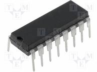
FindIC - A Global Electronic Components Search Engine
Categories
IC Testing Lab AiBOM
English
Home > Popular Part No. >

CD4060 Series Datasheet

CD4060

Logic chip

CD4060 is composed of an oscillator and 14-bit binary serial counter bits. The structure of the oscillator can be an RC or crystal oscillator circuit. When CR is high, the counter is cleared and the oscillator is invalid. All counter bits are master-slave flip-flops. The CD4000 series include CD4060BM and CD4060BC. CD4000 counts in binary at the falling edge of CP1 (and CP0). Use Schmitt triggers on the clock pulse line to limit the clock rise and fall time.

CD4060 Pin Configuration and Function

CD4060Pin Configuration and Function


Pin Number

Pin Name

Description

7,5,4,6,14,13,15,1,2,3

Q3, Q4, Q5, Q6, Q7, Q8, Q9, Q11, Q12, A13

Output pins of the Binary counter 

11

RS

Clock Input Pin for setting clock   frequency 

12

MR

Master Reset

9

CEXT/

External Capacitor to set clock   frequency 

10

REXT/

External Resistor to set clock   frequency 

8

Vss/Ground

Connected to ground of the system 

16

Vdd

Supply Voltage 


CD4060 Series Datasheet

Part No
Picture
Manufacturer
Package
Description
Datasheet
CD4060BE
CD4060BE
TI
SOIC, PDIP

TEXAS INSTRUMENTS CD4060BE Ripple Carry Binary / Divider, 24MHz, 1 Gate, 1Input, 3V to 18V, DIP-16

CD4060BM96
CD4060BM96
TI
SOP16

TEXAS INSTRUMENTS CD4060BM96 Ripple Carry Binary / Divider, 24MHz, 3V to 18V, SOIC-16

CD4060BM
CD4060BM
TI
SOIC

Ripple Carry Binary / Divider, 24MHz, 3V to 18V, SOIC-16

CD4060BMT
CD4060BMT
TI
SOIC, PDIP

Counter/Divider Single 14Bit Binary UP 16Pin SOIC T/R

FindIC user feedback
Question type
Website page questions or suggestions
Data problems or errors
Inquiry for component procurement
other
Comments and suggestions
Contact information
Feedback and contact