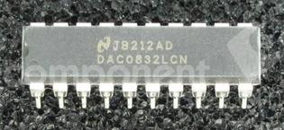
Pin Number | Pin Name | Description |
1 | CS | Chip Select (Active Low) needed to be grounded for enabling the chip |
2 | WR | Write (Active Low) needed to be grounded for successful data transmission |
3 | GND | Ground |
4 | DI3 | Digital Input 3 will take data for conversion |
5 | DI2 | Digital Input 2 will take data for conversion |
6 | DI1 | Digital Input 1 will take data for conversion |
7 | DI0(LSB) | Digital Input 0(Least Significant Bit) will take data for conversion |
8 | VREF | Voltage Reference for the chip is given at this pin |
9 | Rfb | Feedback Resistor will be connected to this pin |
10 | GND | Ground |
11 | IOUT1 | Current Output 1 will give analog output after conversion |
12 | IOUT2 | Current Output 2 will give analog output after conversion |
13 | DI7(MSB) | Digital Input 7(Most Significant Bit) will take data for conversion |
14 | DI6 | Digital Input 6 will take data for conversion |
15 | DI5 | Digital Input 5 will take data for conversion |
16 | DI4 | Digital Input 4 will take data for conversion |
17 | XFER | Transfer Control Signal (Active Low) |
18 | WR2 | Write 2 (Active Low) |
19 | ILE | Input Latch Enable pin needed to be high for successful data transmission |
20 | VCC | Positive Power Supply |
DAC 1CH R-2R 8Bit 20Pin SOIC T/R
TEXAS INSTRUMENTS DAC0832LCN Digital to Analogue Converter, 8Bit, Parallel, 4.75V to 15.75V, DIP, 20Pins
TEXAS INSTRUMENTS DAC0832LCN/NOPB Digital to Analog Converter, 8Bit, Parallel, 5V to 15V, DIP, 20Pins
8Bit P Compatible, Double-Buffered D to A Converters