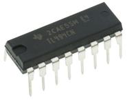
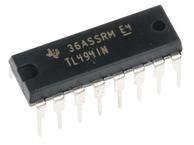
Pin Number | Pin Name | Description |
1 | 1IN+ | Noninverting input to error amplifier 1 |
2 | 1IN- | Inverting input to error amplifier 1 |
3 | FEEDBACK | Input pin for feedback |
4 | DTC | Dead-time control comparator input |
5 | CT | Capacitor terminal used to set the oscillator frequency |
6 | RT | Resistor terminal used to set the oscillator frequency |
7 | GND | Ground Pin |
8 | C1 | The collector terminal of BJT output 1 |
9 | E1 | The emitter terminal of BJT output 1 |
10 | E2 | The emitter terminal of BJT output 2 |
11 | C2 | The collector terminal of BJT output 2 |
12 | VCC | Positive Supply |
13 | OUTPUT CTRL | Selects single-ended/parallel output or push-pull operation |
14 | REF | The 5-V reference regulator output |
15 | 2IN- | Inverting input to error amplifier 2 |
16 | 2IN+ | Noninverting input to error amplifier 2 |
Voltage Mode PWM Controller 40V 200mA 300kHz 16Pin PDIP Tube
Voltage Mode PWM Controller 40V 200mA 300kHz 16Pin SOIC T/R
Voltage Mode PWM Controller 40V 200mA 300kHz 16Pin PDIP Tube
Voltage Mode PWM Controller 40V 200mA 300kHz 16Pin SOIC Tube
Voltage Mode PWM Controller 40V 200mA 300kHz 16Pin SOIC T/R