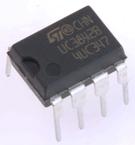
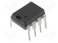
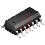
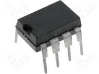
Pin No | Function | Description |
1 | COMP | This pin is the Error Amplifier output and is made available for loop compensation. |
2 | Vfb | This is the inverting input of the Error Amplifier. It is normally connected to the switchingpower supply output through a resistor divider |
3 | ISENSE | A voltage proportional to inductor current is connected to this input. The PWM uses thisinformation to terminate the output switch conduction |
4 | Rt/Ct | The oscillator frequency and maximum Output duty cycle are programmed by connectingresistor RT to Vref and cpacitor CT to ground. Operation to 500kHz is possible |
5 | GROUND | This pin is the combined control circuitry and power ground |
6 | OUTPUT | This output directly drives the gate of a power MOSFET. Peak currents up to 1A are sourcedand sunk by this pin. |
7 | Vcc | This pin is the positive supply of the control IC. |
8 | Vref | This is the reference output. It provides charging current for capacitor CT through resistor RT |
Current Mode PWM Controller 1A 500kHz 8Pin PDIP Tube
PMIC; DC-DC switcher, PWM controller; 1A; 13.5V; DIP8; 1W
UC3842BDG, PWM Current Mode Controller, 1A, 250kHz, 30V, 14Pin SOIC
Current Mode PWM Controller 1A 500kHz 8Pin PDIP Tube
AC to DC Switching Converter Off-Line Switcher 17.5V 500kHz Tube 8Pin PDIP